 W
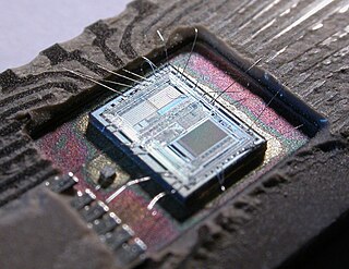
WAn electronic circuit is composed of individual electronic components, such as resistors, transistors, capacitors, inductors and diodes, connected by conductive wires or traces through which electric current can flow. To be referred to as electronic, rather than electrical, generally at least one active component must be present. The combination of components and wires allows various simple and complex operations to be performed: signals can be amplified, computations can be performed, and data can be moved from one place to another.
 W
WAn amplifier, electronic amplifier or (informally) amp is an electronic device that can increase the power of a signal. It is a two-port electronic circuit that uses electric power from a power supply to increase the amplitude of a signal applied to its input terminals, producing a proportionally greater amplitude signal at its output. The amount of amplification provided by an amplifier is measured by its gain: the ratio of output voltage, current, or power to input. An amplifier is a circuit that has a power gain greater than one.
 W
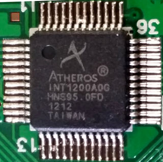
WAn analog front-end is a set of analog signal conditioning circuitry that uses sensitive analog amplifiers, often operational amplifiers, filters, and sometimes application-specific integrated circuits for sensors, radio receivers, and other circuits to provide a configurable and flexible electronics functional block needed to interface a variety of sensors to an antenna, analog-to-digital converter or, in some cases, to a microcontroller.
 W
WIn electronics, an analog-to-digital converter is a system that converts an analog signal, such as a sound picked up by a microphone or light entering a digital camera, into a digital signal. An ADC may also provide an isolated measurement such as an electronic device that converts an analog input voltage or current to a digital number representing the magnitude of the voltage or current. Typically the digital output is a two's complement binary number that is proportional to the input, but there are other possibilities.
 W
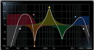
WAn audio filter is a frequency dependent circuit, working in the audio frequency range, 0 Hz to 20 kHz. Audio filters can amplify (boost), pass or attenuate (cut) some frequency ranges. Many types of filters exist for different audio applications including hi-fi stereo systems, musical synthesizers, effects units, sound reinforcement systems, instrument amplifiers and virtual reality systems.
 W
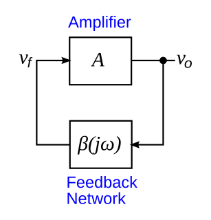
WIn electronics, the Barkhausen stability criterion is a mathematical condition to determine when a linear electronic circuit will oscillate. It was put forth in 1921 by German physicist Heinrich Georg Barkhausen (1881–1956). It is widely used in the design of electronic oscillators, and also in the design of general negative feedback circuits such as op amps, to prevent them from oscillating.
 W
WA Boucherot cell is an electronic filter, used in audio amplifiers to damp high-frequency oscillations that might occur in the absence of loads at high frequencies. Named after Paul Boucherot a Boucherot cell typically consists of a resistor and capacitor in series, usually placed across a load for stability.
 W
WBrokaw bandgap reference is a voltage reference circuit widely used in integrated circuits, with an output voltage around 1.25 V with low temperature dependence. This particular circuit is one type of a bandgap voltage reference, named after Paul Brokaw, the author of its first publication.
 W
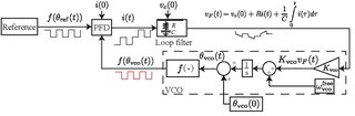
WCharge-pump phase-locked loop (CP-PLL) is a modification of phase-locked loops with phase-frequency detector and square waveform signals. CP-PLL allows for a quick lock of the phase of the incoming signal, achieving low steady state phase error.
 W
WIn electronics, a chopper circuit is any of numerous types of electronic switching devices and circuits used in power control and signal applications. A chopper is a device that converts fixed DC input to a variable DC output voltage directly. Essentially, a chopper is an electronic switch that is used to interrupt one signal under the control of another.
 W
WA clamper is an electronic circuit that fixes either the positive or the negative peak excursions of a signal to a defined value by shifting its DC value. The clamper does not restrict the peak-to-peak excursion of the signal, it moves the whole signal up or down so as to place the peaks at the reference level. A diode clamp consists of a diode, which conducts electric current in only one direction and prevents the signal exceeding the reference value; and a capacitor, which provides a DC offset from the stored charge. The capacitor forms a time constant with the resistor load, which determines the range of frequencies over which the clamper will be effective.
 W
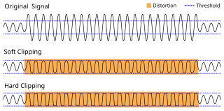
WIn electronics, a clipper is a circuit designed to prevent a signal from exceeding a predetermined reference voltage level. A clipper does not distort the remaining part of the applied waveform. Clipping circuits are used to select, for purposes of transmission, that part of a signal waveform which lies above or below the predetermined reference voltage level.
 W
WIn electronics, a comparator is a device that compares two voltages or currents and outputs a digital signal indicating which is larger. It has two analog input terminals and and one binary digital output . The output is ideally
 W
WAn electronic component is any basic discrete device or physical entity in an electronic system used to affect electrons or their associated fields. Electronic components are mostly industrial products, available in a singular form and are not to be confused with electrical elements, which are conceptual abstractions representing idealized electronic components and elements.
 W
WIn electronics and telecommunications, a crossbar switch is a collection of switches arranged in a matrix configuration. A crossbar switch has multiple input and output lines that form a crossed pattern of interconnecting lines between which a connection may be established by closing a switch located at each intersection, the elements of the matrix. Originally, a crossbar switch consisted literally of crossing metal bars that provided the input and output paths. Later implementations achieved the same switching topology in solid-state electronics. The crossbar switch is one of the principal telephone exchange architectures, together with a rotary switch, memory switch, and a crossover switch.
 W
WA cycloconverter (CCV) or a cycloinverter converts a constant amplitude, constant frequency AC waveform to another AC waveform of a lower frequency by synthesizing the output waveform from segments of the AC supply without an intermediate DC link. There are two main types of CCVs, circulating current type or blocking mode type, most commercial high power products being of the blocking mode type.
 W
WIn electronics, decoupling is the prevention of undesired coupling between subsystems.
 W
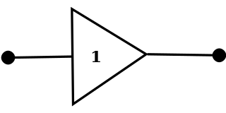
WA digital buffer is an electronic circuit element that is used to isolate the input from the output, providing either no voltage or a voltage that is same as the input voltage. It draws very little current and will not disturb the original circuit. It is also called a unity gain buffer because it provides a gain of 1, which means it provides at most the same voltage as the input voltage, serving no amplification function.
 W
WIn electronics, a digital-to-analog converter is a system that converts a digital signal into an analog signal. An analog-to-digital converter (ADC) performs the reverse function.
 W
WIn electrical engineering, impedance is the opposition to alternating current presented by the combined effect of resistance and reactance in a circuit.
 W
WElectrical resonance occurs in an electric circuit at a particular resonant frequency when the impedances or admittances of circuit elements cancel each other. In some circuits, this happens when the impedance between the input and output of the circuit is almost zero and the transfer function is close to one.
 W
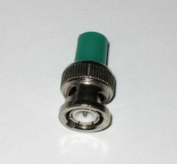
WIn electronics, electrical termination is the practice of ending a transmission line with a device that matches the characteristic impedance of the line. Termination prevents signals from reflecting off the end of the transmission line. Reflections at the ends of unterminated transmission lines cause distortion which can produce ambiguous digital signal levels and mis-operation of digital systems. Reflections in analog signal systems cause such effects as video ghosting, or power loss in radio transmitter transmission lines.
 W
WElectronic filters are a type of signal processing filter in the form of electrical circuits. This article covers those filters consisting of lumped electronic components, as opposed to distributed-element filters. That is, using components and interconnections that, in analysis, can be considered to exist at a single point. These components can be in discrete packages or part of an integrated circuit.
 W
WAn electronic lock is a locking device which operates by means of electric current. Electric locks are sometimes stand-alone with an electronic control assembly mounted directly to the lock. Electric locks may be connected to an access control system, the advantages of which include: key control, where keys can be added and removed without re-keying the lock cylinder; fine access control, where time and place are factors; and transaction logging, where activity is recorded. Electronic locks can also be remotely monitored and controlled, both to lock and to unlock.
 W
WIn electronics, a mixer, or frequency mixer, is a nonlinear electrical circuit that creates new frequencies from two signals applied to it. In its most common application, two signals are applied to a mixer, and it produces new signals at the sum and difference of the original frequencies. Other frequency components may also be produced in a practical frequency mixer.
 W
WGalvanic isolation is a principle of isolating functional sections of electrical systems to prevent current flow; no direct conduction path is permitted. Energy or information can still be exchanged between the sections by other means, such as capacitance, induction or electromagnetic waves, or by optical, acoustic or mechanical means.
 W
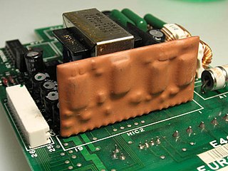
WA hybrid integrated circuit (HIC), hybrid microcircuit, hybrid circuit or simply hybrid is a miniaturized electronic circuit constructed of individual devices, such as semiconductor devices and passive components, bonded to a substrate or printed circuit board (PCB). A PCB having components on a Printed Wiring Board (PWB) is not considered a true hybrid circuit according to the definition of MIL-PRF-38534.
 W
WIn electronics, a limiter is a circuit that allows signals below a specified input power or level to pass unaffected while attenuating (lowering) the peaks of stronger signals that exceed this threshold. Limiting is a type of dynamic range compression. Clipping is an extreme version of limiting.
 W
WThe lumped-element model simplifies the description of the behaviour of spatially distributed physical systems, such as electrical circuits, into a topology consisting of discrete entities that approximate the behaviour of the distributed system under certain assumptions. It is useful in electrical systems, mechanical multibody systems, heat transfer, acoustics, etc. This may be contrasted to distributed parameter systems or models in which the behaviour is distributed spatially and cannot be considered as localized into discrete entities.
 W
WManhattan wiring is a technique for laying out circuits in computer engineering. Inputs to a circuit are aligned into a grid, and the circuit "taps" them perpendicularly. This may be done either virtually or physically. That is, it may be shown this way only in the documentation and the actual circuit may look nothing like that; or it may be laid out that way on the physical chip. Typically, separate lanes are used for the inverted inputs and are tapped separately.
 W
WMesh analysis is a method that is used to solve planar circuits for the currents at any place in the electrical circuit. Planar circuits are circuits that can be drawn on a plane surface with no wires crossing each other. A more general technique, called loop analysis can be applied to any circuit, planar or not. Mesh analysis and loop analysis both make use of Kirchhoff’s voltage law to arrive at a set of equations guaranteed to be solvable if the circuit has a solution. Mesh analysis is usually easier to use when the circuit is planar, compared to loop analysis.
 W
WMOSFET Gate Driver is a specialized circuit that is used to drive the gate of power MOSFETs effectively and efficiently in high-speed switching applications. The addition of high MOSFET Gate drivers are the last step if the turn-on is to fully enhance the conducting channel of the MOSFET technology.
 W
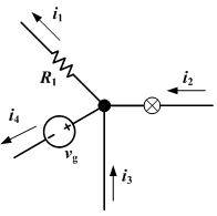
WIn electric circuits analysis, nodal analysis, node-voltage analysis, or the branch current method is a method of determining the voltage between "nodes" in an electrical circuit in terms of the branch currents.
 W
WIn electrical engineering, the passive sign convention (PSC) is a sign convention or arbitrary standard rule adopted universally by the electrical engineering community for defining the sign of electric power in an electric circuit. The convention defines electric power flowing out of the circuit into an electrical component as positive, and power flowing into the circuit out of a component as negative. So a passive component which consumes power, such as an appliance or light bulb, will have positive power dissipation, while an active component, a source of power such as an electric generator or battery, will have negative power dissipation. This is the standard definition of power in electric circuits; it is used for example in computer circuit simulation programs such as SPICE.
 W
WA phase detector or phase comparator is a frequency mixer, analog multiplier or logic circuit that generates a signal which represents the difference in phase between two signal inputs.
 W
WIn electronic logic circuits, a pull-up resistor or pull-down resistor is a resistor used to ensure a known state for a signal. It is typically used in combination with components such as switches and transistors, which physically interrupt the connection of subsequent components to ground or to VCC. When the switch is closed, it creates a direct connection to ground or VCC, but when the switch is open, the rest of the circuit would be left floating. For a switch that connects to ground, a pull-up resistor ensures a well-defined voltage across the remainder of the circuit when the switch is open. Conversely, for a switch that connects to VCC, a pull-down resistor ensures a well-defined ground voltage when the switch is open.
 W
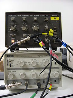
WA pulse generator is either an electronic circuit or a piece of electronic test equipment used to generate rectangular pulses. Pulse generators are used primarily for working with digital circuits, related function generators are used primarily for analog circuits.
 W
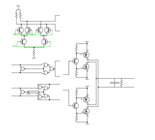
WA push–pull amplifier is a type of electronic circuit that uses a pair of active devices that alternately supply current to, or absorb current from, a connected load. This kind of amplifier can enhance both the load capacity and switching speed.
 W
WA regenerative circuit is an amplifier circuit that employs positive feedback. Some of the output of the amplifying device is applied back to its input so as to add to the input signal, increasing the amplification. One example is the Schmitt trigger, but the most common use of the term is in RF amplifiers, and especially regenerative receivers, to greatly increase the gain of a single amplifier stage.
 W
WIn electronics, a sample and hold circuit is an analog device that samples the voltage of a continuously varying analog signal and holds its value at a constant level for a specified minimum period of time. Sample and hold circuits and related peak detectors are the elementary analog memory devices. They are typically used in analog-to-digital converters to eliminate variations in input signal that can corrupt the conversion process. They are also used in electronic music, for instance to impart a random quality to successively-played notes.
 W
WIn electronics, a Schmitt trigger is a comparator circuit with hysteresis implemented by applying positive feedback to the noninverting input of a comparator or differential amplifier. It is an active circuit which converts an analog input signal to a digital output signal. The circuit is named a trigger because the output retains its value until the input changes sufficiently to trigger a change. In the non-inverting configuration, when the input is higher than a chosen threshold, the output is high. When the input is below a different (lower) chosen threshold the output is low, and when the input is between the two levels the output retains its value. This dual threshold action is called hysteresis and implies that the Schmitt trigger possesses memory and can act as a bistable multivibrator. There is a close relation between the two kinds of circuits: a Schmitt trigger can be converted into a latch and a latch can be converted into a Schmitt trigger.
 W
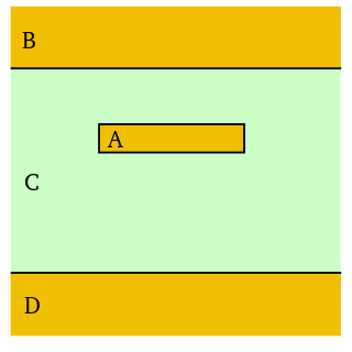
WStripline is a transverse electromagnetic (TEM) transmission line medium invented by Robert M. Barrett of the Air Force Cambridge Research Centre in the 1950s. Stripline is the earliest form of planar transmission line.
 W
WIn circuit theory, a supernode is a theoretical construct that can be used to solve a circuit. This is done by viewing a voltage source on a wire as a point source voltage in relation to other point voltages located at various nodes in the circuit, relative to a ground node assigned a zero or negative charge.
 W
WSupervisory circuits are electronic circuits that monitor one or more parameters of systems such as power supplies and microprocessors which must be maintained within certain limits, and take appropriate action if a parameter goes out of bounds, creating an unacceptable or dangerous situation.
 W
WSupply Voltage Supervisor circuits are used to monitor the supply voltage to embedded and other micro-controller systems for under voltage conditions. If an under voltage condition is detected then the supervisory circuit will reset the controller and keep it in that state as long as the under voltage condition persists. This type of reset is called brown out reset. In many modern day Micro-controllers like Texas Instrument's MSP430 MCU, Brown Out Reset protection is implemented into most MSP430 devices in the case of unstable supply voltages.
 W
WFor the measurement of an alternating current the signal is often converted into a direct current of equivalent value, the root mean square (RMS). Simple instrumentation and signal converters carry out this conversion by filtering the signal into an average rectified value and applying a correction factor. The value of the correction factor applied is only correct if the input signal is sinusoidal.
 W
WIn electrical engineering, an unbalanced circuit is one in which the transmission properties between the ports of the circuit are different for the two poles of each port. It is usually taken to mean that one pole of each port is bonded to a common potential but more complex topologies are possible. This common point is commonly called ground or earth but it may well not actually be connected to electrical ground at all.
 W
WA video decoder is an electronic circuit, often contained within a single integrated circuit chip, that converts base-band analog video signals to digital video. Video decoders commonly allow programmable control over video characteristics such as hue, contrast, and saturation. A video decoder performs the inverse function of a video encoder, which converts raw (uncompressed) digital video to analog video. Video decoders are commonly used in video capture devices and frame grabbers.
 W
WA video line selector is an electronic circuit or device for picking a line from an analog video signal. The input of the circuit is connected to an analog video source, the output triggers an oscilloscope, so display the selected line on the oscilloscope or similar device.
 W
WThe Vienna Rectifier is a pulse-width modulation rectifier, invented in 1993 by Johann W. Kolar.
 W
WThe Warsaw Rectifier is a pulse-width modulation (PWM) rectifier, invented by Włodzimierz Koczara in 1992.
 W
WA window detector circuit, also called window comparator circuit or dual edge limit detector circuits is used to determine whether an unknown input is between two precise reference threshold voltages. It employs two comparators to detect over-voltage or under-voltage.