 W
WTechnical drawing, drafting or drawing, is the act and discipline of composing drawings that visually communicate how something functions or is constructed.
 W
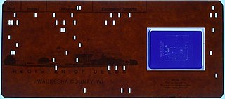
WAn aperture card is a type of punched card with a cut-out window into which a chip of microfilm is mounted. Such a card is used for archiving or for making multiple inexpensive copies of a document for ease of distribution. The card is typically punched with machine-readable metadata associated with the microfilm image, and printed across the top of the card for visual identification; it may also be punched by hand in the form of an edge-notched card. The microfilm chip is most commonly 35mm in height, and contains an optically reduced image, usually of some type of reference document, such as an engineering drawing, that is the focus of the archiving process. Machinery exists to automatically store, retrieve, sort, duplicate, create, and digitize cards with a high level of automation.
 W
WAn architectural drawing or architect's drawing is a technical drawing of a building that falls within the definition of architecture. Architectural drawings are used by architects and others for a number of purposes: to develop a design idea into a coherent proposal, to communicate ideas and concepts, to convince clients of the merits of a design, to assist a building contractor to construct it based on design intent, as a record of the design and planned development, or to make a record of a building that already exists.
 W
WIn the field of architecture an architectural plan is a design and planning for a building, and can contain architectural drawings, specifications of the design, calculations, time planning of the building process, and other documentation.
 W
WArchitectural rendering, architectural illustration, or architectural visualization is the art of creating three-dimensional images or animations showing the attributes of a proposed architectural design.
 W
WM. (Mary) Louise Baker was an American archaeological illustrator, resident artist at the University of Pennsylvania Museum of Archaeology and Anthropology (1908-1936), and an art teacher at the George School.
 W
WA bird's-eye view is an elevated view of an object from above, with a perspective as though the observer were a bird, often used in the making of blueprints, floor plans, and maps. It can be an aerial photograph, but also a drawing.
 W
WA blueprint is a reproduction of a technical drawing or engineering drawing using a contact print process on light-sensitive sheets. Introduced by Sir John Herschel in 1842, the process allowed rapid and accurate production of an unlimited number of copies. It was widely used for over a century for the reproduction of specification drawings used in construction and industry. The blueprint process was characterized by white lines on a blue background, a negative of the original. The process was not able to reproduce color or shades of grey.
 W
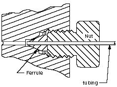
WCentre-to-centre distance is a concept for distances, also called on-center spacing, heart distance, and pitch.
 W
WA civil drawing, or site drawing, is a type of technical drawing that shows information about grading, landscaping, or other site details. These drawings are intended to give a clear picture of all things in a construction site to a civil engineer.
 W
WIn geometry and science, a cross section is the non-empty intersection of a solid body in three-dimensional space with a plane, or the analog in higher-dimensional spaces. Cutting an object into slices creates many parallel cross-sections. The boundary of a cross-section in three-dimensional space that is parallel to two of the axes, that is, parallel to the plane determined by these axes, is sometimes referred to as a contour line; for example, if a plane cuts through mountains of a raised-relief map parallel to the ground, the result is a contour line in two-dimensional space showing points on the surface of the mountains of equal elevation.
 W
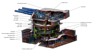
WA cutaway drawing, also called a cutaway diagram is a 3D graphics, drawing, diagram and or illustration, in which surface elements of a three-dimensional model are selectively removed, to make internal features visible, but without sacrificing the outer context entirely.
 W
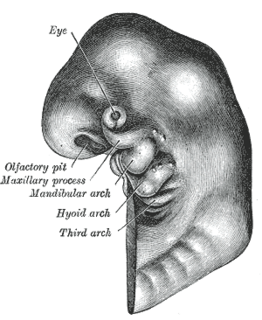
WEmbryo drawing is the illustration of embryos in their developmental sequence. In plants and animals, an embryo develops from a zygote, the single cell that results when an egg and sperm fuse during fertilization. In animals, the zygote divides repeatedly to form a ball of cells, which then forms a set of tissue layers that migrate and fold to form an early embryo. Images of embryos provide a means of comparing embryos of different ages, and species. To this day, embryo drawings are made in undergraduate developmental biology lessons.
 W
WAn engineering drawing is a type of technical drawing that is used to convey information about an object. A common use is to specify the geometry necessary for the construction of a component and is called a detail drawing. Usually, a number of drawings are necessary to completely specify even a simple component. The drawings are linked together by a master drawing or assembly drawing which gives the drawing numbers of the subsequent detailed components, quantities required, construction materials and possibly 3D images that can be used to locate individual items. Although mostly consisting of pictographic representations, abbreviations and symbols are used for brevity and additional textual explanations may also be provided to convey the necessary information.
 W
WAn engineering technician is a professional trained in skills and techniques related to a specific branch of technology, with a practical understanding of the relevant engineering concepts. Engineering technicians often assist engineers and engineering technologists in projects relating to research and development, or focus on post-development activities like implementation or operation. An engineering technician is between a skilled craft worker and an engineering technologist.
 W
WAn engineering technologist is a professional trained in certain aspects of development and implementation of a respective area of technology. Engineering technology education is even more applied and less theoretical than engineering education, though in a broad sense both have a focus on practical application. Engineering technologists often assist engineers but after years of experience, they can also become engineers. Like engineers, areas where engineering technologists can work include product design, fabrication and testing. Also as with engineers, engineering technologists sometimes rise to senior management positions in industry or become entrepreneurs.
 W
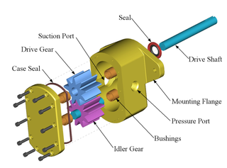
WAn exploded view drawing is a diagram, picture, schematic or technical drawing of an object, that shows the relationship or order of assembly of various parts.
 W
WIn architecture and building engineering, a floor plan is a drawing to scale, showing a view from above, of the relationships between rooms, spaces, traffic patterns, and other physical features at one level of a structure.
 W
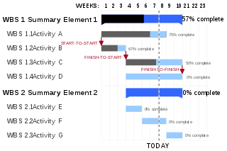
WA Gantt chart is a type of bar chart that illustrates a project schedule, named after its inventor, Henry Gantt (1861–1919), who designed such a chart around the years 1910–1915. Modern Gantt charts also show the dependency relationships between activities and the current schedule status.
 W
WGeometric Dimensioning and Tolerancing (GD&T) is a system for defining and communicating engineering tolerances. It uses a symbolic language on engineering drawings and computer-generated three-dimensional solid models that explicitly describe nominal geometry and its allowable variation. It tells the manufacturing staff and machines what degree of accuracy and precision is needed on each controlled feature of the part. GD&T is used to define the nominal geometry of parts and assemblies, to define the allowable variation in form and possible size of individual features, and to define the allowable variation between features.Dimensioning specifications define the nominal, as-modeled or as-intended geometry. One example is a basic dimension. Tolerancing specifications define the allowable variation for the form and possibly the size of individual features, and the allowable variation in orientation and location between features. Two examples are linear dimensions and feature control frames using a datum reference.
 W
WGraph paper, coordinate paper, grid paper, or squared paper is writing paper that is printed with fine lines making up a regular grid. The lines are often used as guides for plotting graphs of functions or experimental data and drawing curves. It is commonly found in mathematics and engineering education settings and in laboratory notebooks. Graph paper is available either as loose leaf paper or bound in notebooks.
 W
WGraphic communication as the name suggests is communication using graphic elements. These elements include symbols such as glyphs and icons, images such as drawings and photographs, and can include the passive contributions of substrate, colour and surroundings. It is the process of creating, producing, and distributing material incorporating words and images to convey data, concepts, and emotions.
 W
WHatching is an artistic technique used to create tonal or shading effects by drawing closely spaced parallel lines. When lines are placed at an angle to one another, it is called cross-hatching.
 W
WA house plan is a set of construction or working drawings that define all the construction specifications of a residential house such as the dimensions, materials, layouts, installation methods and techniques.
 W
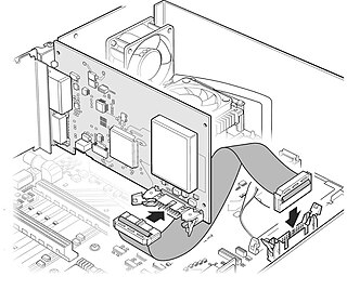
WTechnical Illustration is illustration meant to visually communicate information of a technical nature. Technical illustrations can be components of technical drawings or diagrams. Technical illustrations in general aim "to generate expressive images that effectively convey certain information via the visual channel to the human observer".
 W
WA linear scale, also called a bar scale, scale bar, graphic scale, or graphical scale, is a means of visually showing the scale of a map, nautical chart, engineering drawing, or architectural drawing. A scale bar is common element of map layouts.
 W
WMechanical systems drawing is a type of technical drawing that shows information about heating, ventilating, air conditioning and transportation around the building. It is a powerful tool that helps analyze complex systems. These drawings are often a set of detailed drawings used for construction projects; it is a requirement for all HVAC work. They are based on the floor and reflected ceiling plans of the architect. After the mechanical drawings are complete, they become part of the construction drawings, which is then used to apply for a building permit. They are also used to determine the price of the project.
 W
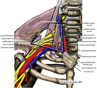
WA medical illustration is a form of biological illustration that helps to record and disseminate medical, anatomical, and related knowledge.
 W
WThe National Geographical Organization of Iran or National Geographical Organization of the Armed Forces of Iran is an Iranian government agency affiliated to the Ministry of Defence and Armed Forces Logistics of Iran, which has been established to prepare quick and accurate access spatial information of the country and other areas required by the Armed Forces of Iran.
 W
WPaper size standards govern the size of sheets of paper used as writing paper, stationery, cards, and for some printed documents.
 W
WThe parallel motion is a mechanical linkage invented by the Scottish engineer James Watt in 1784 for the double-acting Watt steam engine. It allows a rod moving practically straight up and down to transmit motion to a beam moving in an arc, without putting significant sideways strain on the rod.
 W
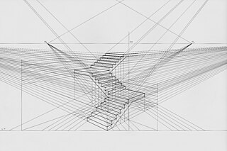
WLinear or point-projection perspective is one of two types of graphical projection perspective in the graphic arts; the other is parallel projection. Linear perspective is an approximate representation, generally on a flat surface, of an image as it is seen by the eye. The most characteristic features of linear perspective are that objects appear smaller as their distance from the observer increases, and that they are subject to foreshortening, meaning that an object's dimensions along the line of sight appear shorter than its dimensions across the line of sight. All objects will recede to points in the distance, usually along the horizon line, but also above and below the horizon line depending on the view used.
 W
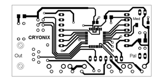
WA photolith film is a transparent film, made with some sort of transparent plastic. Nowadays, with the use of laser printers and computers, the photolith film can be based on polyester, vegetable paper or laser film paper. It is mainly used in all photolithography processes.
 W
WIn archaeological excavation, a plan is a drawn record of features and artifacts in the horizontal plane.
 W
WPlans are a set of drawings or two-dimensional diagrams used to describe a place or object, or to communicate building or fabrication instructions. Usually plans are drawn or printed on paper, but they can take the form of a digital file.
 W
WIn geometric dimensioning and tolerancing, a projected tolerance zone is defined to predict the final dimensions and locations of features on a component or assembly subject to tolerance stack-up.
 W
WThe Schmidt net is a manual drafting method for the Lambert azimuthal equal-area projection using graph paper. It results in one lateral hemisphere of the Earth with the grid of parallels and meridians. The method is common in the geophysical sciences.
 W
WIn science and engineering, a semi-log plot/graph or semi-logarithmic plot/graph has one axis on a logarithmic scale, the other on a linear scale. It is useful for data with exponential relationships, where one variable covers a large range of values, or to zoom in and visualize that - what seems to be a straight line in the beginning - is in fact the slow start of a logarithmic curve that is about to spike and changes are much bigger than thought initially.
 W
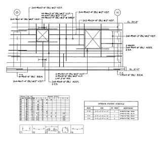
WA shop drawing is a drawing or set of drawings produced by the contractor, supplier, manufacturer, subcontractor, consultants, or fabricator. Shop drawings are typically required for prefabricated components. Examples of these include: elevators, structural steel, trusses, pre-cast concrete, windows, appliances, cabinets, air handling units, and millwork. Also critical are the installation and coordination shop drawings of the MEP trades such as sheet metal ductwork, piping, plumbing, fire protection, and electrical. Shop drawings are produced by contractors and suppliers under their contract with the owner. The shop drawing is the manufacturer’s or the contractor’s drawn version of information shown in the construction documents. The shop drawing normally shows more detail than the construction documents. It is drawn to explain the fabrication and/or installation of the items to the manufacturer’s production crew or contractor's installation crews. The style of the shop drawing is usually very different from that of the architect’s drawing. The shop drawing’s primary emphasis is on the particular product or installation and excludes notation concerning other products and installations, unless integration with the subject product is necessary.
 W
WA site plan or a plot plan is a type of drawing used by architects, landscape architects, urban planners, and engineers which shows existing and proposed conditions for a given area, typically a parcel of land which is to be modified. Sites plan typically show buildings, roads, sidewalks and paths/trails, parking, drainage facilities, sanitary sewer lines, water lines, lighting, and landscaping and garden elements.
 W
WSunspot drawing or sunspot sketching is the act of drawing sunspots. Sunspots are darker spots on the Sun's photosphere. Their prediction is very important for radio communication because they are strongly associated with solar activity, which can seriously damage radio equipment.
 W
WDrafting tools may be used for measurement and layout of drawings, or to improve the consistency and speed of creation of standard drawing elements. Tools such as pens and pencils mark the drawing medium. Other tools such as straight edges, assist the operator in drawing straight lines, or assist the operator in drawing complicated shapes repeatedly. Various scales and the protractor are used to measure the lengths of lines and angles, allowing accurate scale drawing to be carried out.The compass is used to draw arcs and circles. A drawing board was used to hold the drawing media in place; later boards included drafting machines that sped the layout of straight lines and angles. Tools such as templates and lettering guides assisted in the drawing of repetitive elements such as circles, ellipses, schematic symbols and text. Other auxiliary tools were used for special drawing purposes or for functions related to the preparation and revision of drawings. The tools used for manual technical drawing have been displaced by the advent of computer-aided drawing, drafting and design (CADD).
 W
WWhiteprint describes a document reproduction produced by using the diazo chemical process. It is also known as the blue-line process since the result is blue lines on a white background. It is a contact printing process which accurately reproduces the original in size, but cannot reproduce continuous tones or colors. The light-sensitivity of the chemicals used was known in the 1890s and several related printing processes were patented at that time. Whiteprinting replaced the blueprint process for reproducing architectural and engineering drawings because the process was simpler and involved fewer toxic chemicals. A blue-line print is not permanent and will fade if exposed to light for weeks or months, but a drawing print that lasts only a few months is sufficient for many purposes.
 W
WA worm's-eye view is a view of an object from below, as though the observer were a worm; the opposite of a bird's-eye view.