 W
WAn electronic oscillator is an electronic circuit that produces a periodic, oscillating electronic signal, often a sine wave or a square wave. Oscillators convert direct current (DC) from a power supply to an alternating current (AC) signal. They are widely used in many electronic devices ranging from simplest clock generators to digital instruments and complex computers and peripherals etc. Common examples of signals generated by oscillators include signals broadcast by radio and television transmitters, clock signals that regulate computers and quartz clocks, and the sounds produced by electronic beepers and video games.
 W
WThe 555 timer IC is an integrated circuit (chip) used in a variety of timer, delay, pulse generation, and oscillator applications. Derivatives provide two (556) or four (558) timing circuits in one package. It was commercialized in 1972 by Signetics and it was reported to still be in wide use as of 2013. Numerous companies have made the original bipolar timers and similar low-power CMOS timers too. In 2017, it was said over a billion 555 timers are produced annually by some estimates, and "probably the most popular integrated circuit ever made."
 W
WThe Armstrong oscillator is an electronic oscillator circuit which uses an inductor and capacitor to generate an oscillation. It is the earliest oscillator circuit, invented by US engineer Edwin Armstrong in 1912 and independently by Austrian engineer Alexander Meissner in 1913, and was used in the first vacuum tube radio transmitters. It is sometimes called a tickler oscillator because its distinguishing feature is that the feedback signal needed to produce oscillations is magnetically coupled into the tank inductor in the input circuit by a "tickler coil" (L2, right) in the output circuit. Assuming the coupling is weak, but sufficient to sustain oscillation, the oscillation frequency f is determined primarily by the tank circuit (L1 and C in the figure on the right) and is approximately given by
 W
WIn a radio receiver, a beat frequency oscillator or BFO is a dedicated oscillator used to create an audio frequency signal from Morse code radiotelegraphy (CW) transmissions to make them audible. The signal from the BFO is mixed with the received signal to create a heterodyne or beat frequency which is heard as a tone in the speaker. BFOs are also used to demodulate single-sideband (SSB) signals, making them intelligible, by essentially restoring the carrier that was suppressed at the transmitter. BFOs are sometimes included in communications receivers designed for short wave listeners; they are almost always found in communication receivers for amateur radio, which often receive CW and SSB signals.
 W
WA blocking oscillator is a simple configuration of discrete electronic components which can produce a free-running signal, requiring only a resistor, a transformer, and one amplifying element such as a transistor or vacuum tube. The name is derived from the fact that the amplifying element is cut-off or "blocked" for most of the duty cycle, producing periodic pulses on the principle of a relaxation oscillator. The non-sinusoidal output is not suitable for use as a radio-frequency local oscillator, but it can serve as a timing generator, to power lights, LEDs, Elwire, or small neon indicators. If the output is used as an audio signal, the simple tones are also sufficient for applications such as alarms or a Morse code practice device. Some cameras use a blocking oscillator to strobe the flash prior to a shot to reduce the red-eye effect.
 W
WA carrier recovery system is a circuit used to estimate and compensate for frequency and phase differences between a received signal's carrier wave and the receiver's local oscillator for the purpose of coherent demodulation.
 W
WChua's circuit is a simple electronic circuit that exhibits classic chaotic behavior. This means roughly that it is a "nonperiodic oscillator"; it produces an oscillating waveform that, unlike an ordinary electronic oscillator, never "repeats". It was invented in 1983 by Leon O. Chua, who was a visitor at Waseda University in Japan at that time. The ease of construction of the circuit has made it a ubiquitous real-world example of a chaotic system, leading some to declare it "a paradigm for chaos".
 W
WA crystal oscillator is an electronic oscillator circuit that uses the mechanical resonance of a vibrating crystal of piezoelectric material to create an electrical signal with a constant frequency. This frequency is often used to keep track of time, as in quartz wristwatches, to provide a stable clock signal for digital integrated circuits, and to stabilize frequencies for radio transmitters and receivers. The most common type of piezoelectric resonator used is the quartz crystal, so oscillator circuits incorporating them became known as crystal oscillators, but other piezoelectric materials including polycrystalline ceramics are used in similar circuits.
 W
WA crystal oven is a temperature-controlled chamber used to maintain the quartz crystal in electronic crystal oscillators at a constant temperature, in order to prevent changes in the frequency due to variations in ambient temperature. An oscillator of this type is known as an oven-controlled crystal oscillator This type of oscillator achieves the highest frequency stability possible with a crystal. They are typically used to control the frequency of radio transmitters, cellular base stations, military communications equipment, and for precision frequency measurement.
 W
WIn electronics, a delay-locked loop (DLL) is a digital circuit similar to a phase-locked loop (PLL), with the main difference being the absence of an internal voltage-controlled oscillator, replaced by a delay line.
 W
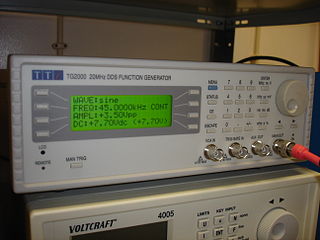
WDirect digital synthesis (DDS) is a method employed by frequency synthesizers used for creating arbitrary waveforms from a single, fixed-frequency reference clock. DDS is used in applications such as signal generation, local oscillators in communication systems, function generators, mixers, modulators, sound synthesizers and as part of a digital phase-locked loop.
 W
WIn electronics, the dynatron oscillator, invented in 1918 by Albert Hull at General Electric, is an obsolete vacuum tube electronic oscillator circuit which uses a negative resistance characteristic in early tetrode vacuum tubes, caused by a process called secondary emission. It was the first negative resistance vacuum tube oscillator. The dynatron oscillator circuit was used to a limited extent as beat frequency oscillators (BFOs), and local oscillators in vacuum tube radio receivers as well as in scientific and test equipment from the 1920s to the 1940s but became obsolete around World War 2 due to the variability of secondary emission in tubes.
 W
WThe extended interaction oscillator (EIO) is a linear-beam vacuum tube designed to convert direct current to RF power. The conversion mechanism is the space charge wave process whereby velocity modulation in an electron beam transforms to current or density modulation with distance.
 W
WGrid dip oscillator (GDO), also called grid dip meter, gate dip meter, dip meter, or just dipper, is a type of electronic instrument that measures the resonant frequency of unconnected, nearby radio frequency circuits. It is a variable frequency oscillator that circulates a small-amplitude signal through an exposed coil, whose electromagnetic field can interact with adjacent circuitry. The oscillator loses power when its coil is near a circuit that resonates at the same frequency. A meter on the GDO registers the amplitude drop, or "dip", hence the name.
 W
WThe HP200A was the first product made by Hewlett-Packard and was manufactured in David Packard's garage in Palo Alto, California.
 W
WA joule thief is a minimalist self-oscillating voltage booster that is small, low-cost, and easy to build, typically used for driving small loads. This circuit is also known by other names such as blocking oscillator, joule ringer, vampire torch. It can use nearly all of the energy in a single-cell electric battery, even far below the voltage where other circuits consider the battery fully discharged ; hence the name, which suggests the notion that the circuit is stealing energy or "joules" from the source - the term is a pun on "jewel thief". The circuit is a variant of the blocking oscillator that forms an unregulated voltage boost converter. The output voltage is increased at the expense of higher current draw on the input, but the integrated (average) current of the output is lowered and brightness of a luminescence decreased.
 W
WA multivibrator is an electronic circuit used to implement a variety of simple two-state devices such as relaxation oscillators, timers and flip-flops. It consists of two amplifying devices cross-coupled by resistors or capacitors. The first multivibrator circuit, the astable multivibrator oscillator, was invented by Henri Abraham and Eugene Bloch during World War I. They called their circuit a "multivibrator" because its output waveform was rich in harmonics.
 W
WThe NE612 is an integrated circuit for processing of signals, such as in the transmission of radio signals. It comprises an oscillator and a mixer. It can handle signal frequencies up to 500 MHz and local oscillator frequencies up to 200 MHz. The mixer is a “Gilbert cell” multiplier configuration which provides both a gain of 14 dB and a noise figure of 5 dB at 45 MHz. The IC belongs to a family of the following ICs: NE602, SA602, NE612 and SA612. It is widely used in amateur radio applications, e.g. in the commercial Elecraft products, and others.
 W
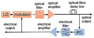
WAn opto-electronic oscillator (OEO) is an optoelectronic circuit that produces repetitive electronic sine wave and/or modulated optical continuous wave signals.
 W
WA parametric oscillator is a driven harmonic oscillator in which the oscillations are driven by varying some parameter of the system at some frequency, typically different from the natural frequency of the oscillator. A simple example of a parametric oscillator is a child pumping a playground swing by periodically standing and squatting to increase the size of the swing's oscillations. The child's motions vary the moment of inertia of the swing as a pendulum. The "pump" motions of the child must be at twice the frequency of the swing's oscillations. Examples of parameters that may be varied are the oscillator's resonance frequency and damping .
 W
WA phase-locked loop or phase lock loop (PLL) is a control system that generates an output signal whose phase is related to the phase of an input signal. There are several different types; the simplest is an electronic circuit consisting of a variable frequency oscillator and a phase detector in a feedback loop. The oscillator generates a periodic signal, and the phase detector compares the phase of that signal with the phase of the input periodic signal, adjusting the oscillator to keep the phases matched.
 W
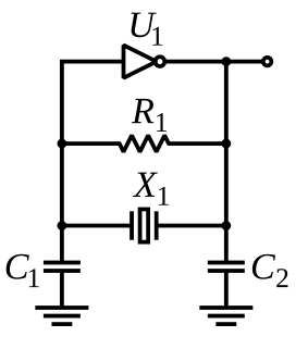
WThe Pierce oscillator is a type of electronic oscillator particularly well-suited for use in piezoelectric crystal oscillator circuits. Named for its inventor, George W. Pierce (1872–1956), the Pierce oscillator is a derivative of the Colpitts oscillator. Virtually all digital IC clock oscillators are of Pierce type, as the circuit can be implemented using a minimum of components: a single digital inverter, one resistor, two capacitors, and the quartz crystal, which acts as a highly selective filter element. The low manufacturing cost of this circuit and the outstanding frequency stability of the quartz crystal give it an advantage over other designs in many consumer electronics applications.
 W
WQuartz clocks and quartz watches are timepieces that use an electronic oscillator regulated by a quartz crystal to keep time. This crystal oscillator creates a signal with very precise frequency, so that quartz clocks and watches are at least an order of magnitude more accurate than mechanical clocks. Generally, some form of digital logic counts the cycles of this signal and provides a numeric time display, usually in units of hours, minutes, and seconds.
 W
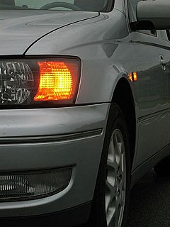
WIn electronics a relaxation oscillator is a nonlinear electronic oscillator circuit that produces a nonsinusoidal repetitive output signal, such as a triangle wave or square wave. The circuit consists of a feedback loop containing a switching device such as a transistor, comparator, relay, op amp, or a negative resistance device like a tunnel diode, that repetitively charges a capacitor or inductor through a resistance until it reaches a threshold level, then discharges it again. The period of the oscillator depends on the time constant of the capacitor or inductor circuit. The active device switches abruptly between charging and discharging modes, and thus produces a discontinuously changing repetitive waveform. This contrasts with the other type of electronic oscillator, the harmonic or linear oscillator, which uses an amplifier with feedback to excite resonant oscillations in a resonator, producing a sine wave. Relaxation oscillators are used to produce low frequency signals for applications such as blinking lights(turn signals) and electronic beepers and in voltage controlled oscillators (VCOs), inverters and switching power supplies, dual-slope analog to digital converters, and function generators.
 W
WA ring oscillator is a device composed of an odd number of NOT gates in a ring, whose output oscillates between two voltage levels, representing true and false. The NOT gates, or inverters, are attached in a chain and the output of the last inverter is fed back into the first.
 W
WA tri-tet oscillator is a crystal-controlled vacuum tube electronic oscillator circuit. It is a type of electron-coupled oscillator (ECO), which uses a tetrode or pentode tube.
 W
WA Vackář oscillator is a wide range variable frequency oscillator (VFO) that strives for a near constant output amplitude over its frequency range. It is similar to a Colpitts oscillator or a Clapp oscillator, but those designs do not have a constant output amplitude when tuned.
 W
WIn dynamics, the Van der Pol oscillator is a non-conservative oscillator with non-linear damping. It evolves in time according to the second-order differential equation:
 W
WA voltage-controlled oscillator (VCO) is an electronic oscillator whose oscillation frequency is controlled by a voltage input. The applied input voltage determines the instantaneous oscillation frequency. Consequently, a VCO can be used for frequency modulation (FM) or phase modulation (PM) by applying a modulating signal to the control input. A VCO is also an integral part of a phase-locked loop.
 W
WA Wien bridge oscillator is a type of electronic oscillator that generates sine waves. It can generate a large range of frequencies. The oscillator is based on a bridge circuit originally developed by Max Wien in 1891 for the measurement of impedances. The bridge comprises four resistors and two capacitors. The oscillator can also be viewed as a positive gain amplifier combined with a bandpass filter that provides positive feedback. Automatic gain control, intentional non-linearity and incidental non-linearity limit the output amplitude in various implementations of the oscillator.